Supply board description
Status: Successfully used for Eurobot 2012.
The power supply board provides the following outputs from a 12 V lead acid battery:
- 5 V @ 3 A, for digital boards,
- 6 V @ 3 A, supposed to be used for servo motors,
- 24 V @ 1.2 A, for industrial sensors.
When an external power (between 8 V and 18 V) is plugged into the supply board, it is used to supply the robot instead of the battery. This external power is also used to charge the 12 V battery and another 24 V battery (used for high current actuators).
The schematic of the card is separated to some parts. Each can be reused into several electronics designs. Parts on the left concerns the input of the card, on the middle the regulation stages, supply selection and voltage visualization. Then, parts on the right represent the outputs of the card.
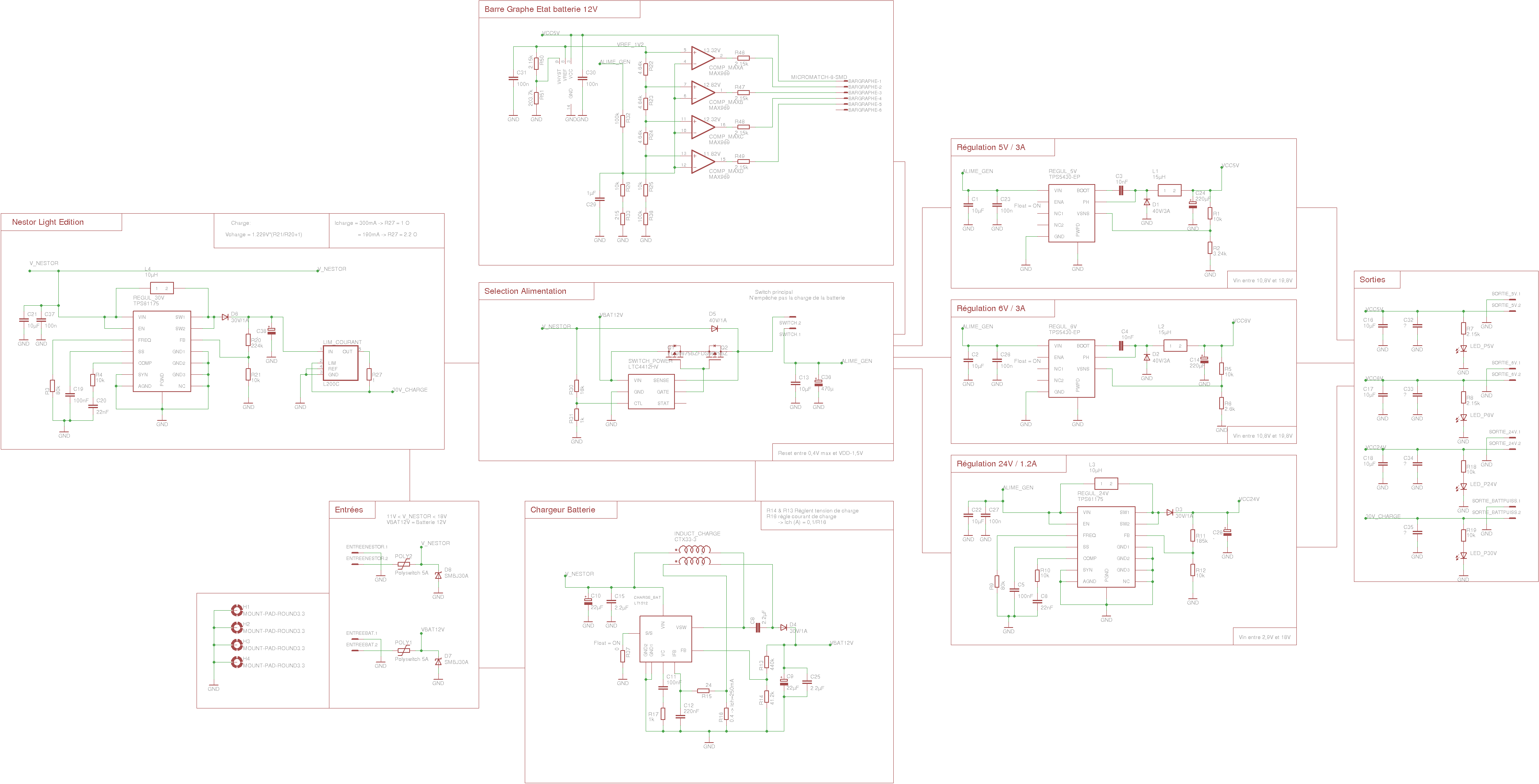
(see Eagle schematic for easier viewing)
Inputs section
Inputs section is constituted of two identical parts: one is for the battery and the second is for the external power source (which name’s Nestor). Each part has an over voltage protection (made by SMBJ30A diode) which works with an over current protection (Polyswitch). When a problem happens, the diode become passing and then the polyswitch detect this short circuit and cut the connection. It will rearm itself when the problem will disappear. Max voltage and current can be customizable by choosing the corresponding polyswitch and diode.
Nestor Light Edition
This section manages the charge of the 24V battery when the external supply power is plugged. This system provides a 28V supply, current limited at 300mA. We use two components for doing this job: a LT1618 is a step-up and will provide the voltage, and then a L200C will limit the current.
Voltage Step-up
The TPS61175 is a switching regulator and can build a 28V voltage from a voltage below 18V. We have to choose a switching frequency: this one is selected by a resistor plugged at the FREQ pin. A high frequency allow to use smaller package and value for the capacitors and inductors, but reduce the power conversion efficiency.
The output voltage can be chosen with the two resistor R20 & R21 at the end part of the regulator (connected at FB). This one can be calculated with the following formula: Vch = 1.229 x (R21/R20+1).
Current limitation
The L200C can regulate the output current (and can regulate a voltage, but we don’t care). What we have to do is just place a resistor between the LIM and OUT signal. For example, a resistor of 1Ohm will regulate at 300mA and a 2.2Ohm will regulate at 190mA.
The 24V battery is plugged just after the L200C, so we need to put a diode between for avoiding any current from battery to regulation circuit.
Supply selection
When plugging an external supply, the 12V battery needs to be isolated from the rest of circuit. The LTC4412HV is a component which allows to control some MOS transistors when a second input supply is detected. By default, the component detects the second source with the SENSE pin (if this one gets a higher voltage than VIN). But this imposes that the second source gets a higher voltage than the battery. In our case, the second source can be below the voltage of the battery (because battery voltage grows with the charge).
We use the CTL pin for choosing the external supply when it is present, no matter that this one’s higher or below the battery voltage. However, be careful because the CTL pin is effective when a voltage of 0.35V is applied. So when you plug in or out an external supply, a drop of voltage can happen. A voltage divider with two resistors reduces this effect.
When external supply is plugged, MOS transistors cut the connection from 12V battery to the rest of the circuit and the external supply gives the current through the D5 diode.
Battery charger
The battery charger is constituted of the LT1512 component. It allows to charge a battery, no matter the input voltage is higher or below the battery voltage. The input voltage value should not be higher than 40V-Vbat. For a 12V battery, input voltage should be 28V Max.
The final voltage charge is defined with the R14 and R15 resistors by the following formula:
Then, the charge current is choosen with R16:
Ich (A) = 0.1 / R16
Bar-Graph
The Bar-graph permits to check the 12V battery voltage with 4 DELs. MAX969 is a component build with 4 voltage comparators. It is capable to generate a reference voltage of 1.2V. We use this voltage and compare it to our 12V battery voltage (this one is reduced by some voltage dividers). Resistors values are calculated in function of the different stages of voltage desired. When a stage is reached, the output comparator will be low, then, the DEL emits light.
The DELs are placed on a small external card, between the 5V and the output of a comparator.
5V/6V Regulation
5 and 6V are generated with the 12V battery with the TPS5430. This component is a switching regulator with high current capability (up to 3A typically). It is over temperature and short circuit protected. The input voltage can be up to 18V.
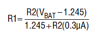
The output voltage is selected with two resistors (R1&R2 for 5V, and R5&R6 for 6V). The relation which determines this value is the following:
![]()
Note: This component come with a PowerPad package. It is recommended to connect the pad below the component to ground (for dissipating the temperature).
24V Regulation
The 24V regulation is generated by the same step-up used in Nestor Light: the TPS31175. The only things which change are the resistors in output for regulating at 24V.
This part can provide a clean 24V up to 1.2A. Max input voltage should be 18V.
Output stage
The output stage consists just at some decoupling capacitors and some DEL for checking the output voltages are present. Nothing to say here =).