From digital/asserv/doc:
Asserv: Microcontroller based motor control
Author
Ni
Encoders
To control a motor using a PID, a feedback is needed. Its role is to measure the position of the rotor shaft. One commonly used solution is the optical incremental encoder. This encoder has a determined number of positions. It will output an impulsion each time its position change, with a second output which make it possible to determine the rotation direction.
Some encoders also output an index signal used to know the exact shaft position after initialisation.
Encoders signals
The two output channels are usually named A and B. The encoder wheel will generate two square waveforms, with a 90 degrees phase shift. The B channel will generate counting impulsions, the A channel will be used to determine the direction (actually, A and B can be swapped). Here is a example waveform for an encoder turning smoothly in a given direction:
A:   _____------______------______----
B:   --______------______------______-
Pos:   ^0          ^1          ^2
The ^ symbol show the transition between positions. Here is a more
chaotic movement:
A:   _____--------------------______-------______----
B:   --______--------------------______---______-----
Pos:   ^0                        ^1             ^0
After the transition to the position 0, the rotor stayed steady, then continued to the position 1. Finally, it continued in the same direction for less than a position and returned to position 0.
If this does not seems clear to you, wait, there is a simpler view below.
Encoders which are sold for 500 positions will generate 500 positive edges per turn on each channel.
Actually, the resolution of the encoder can be improved, and moreover, with a simpler view of the signal. The A and B channels can be seen as a Grey coding of four sub-positions (the Grey code defines a sequence of binary number where each number differ from the previous or the following one by one and only one bit):
| B | A | Position |
|---|---|---|
| 0 | 0 | 0 |
| 0 | 1 | 1 |
| 1 | 1 | 2 |
| 1 | 0 | 3 |
With this system, it is easy to know what is the rotation direction. Just look at the sub-positions and determine if the new one is before or after the old one.
Here is the same waveform with this new way of thinking:
A:    _____------______------______-----
B:    --______------______------______--
SPos:   ^0 ^1 ^2 ^3 ^0 ^1 ^2 ^3 ^0 ^1 ^2
Pos:     0  1  2  3  4  5  6  7  8  9 10
SPos is the sub-position.
Decoding, the D flip-flop schematic
One commonly used schematic to decode this kind of signal uses a single D flip-flop. This kind of flip-flop copies its D input to its Q output on each clock rising edge. Here is this schematic:
TODO: insert the schematic
On each B rising edge, A is copied to the flip-flop output. If the rotor is going forward, Q will be low. If the rotor is going backward, Q will be high. The B signal is also connected to the clock input of a counter and Q to its direction input.
This schematic has one major drawback. Look at this waveform:
A:     ______------__________------______
B:     ___------______----______------___
SPos:  0  ^3 ^2 ^1 ^0 ^3  ^0 ^1 ^2 ^3 ^0
Pos:   0  -1 -2 -3 -4 -5  -4 -3 -2 -1  0
Q:     _________________________---------
Count:    ^-          ^-        ^+
Pos:   0  -1          -2        -1
TODO: to better show the problem, the counter should be defined. If it count on the rising edge, does it take the old or the new value of Q (new for a software counter, old for a programmable logic one for example).
Decoding, the four states automaton
This decoding use the observation done before about the Grey encoding of the four sub-positions.
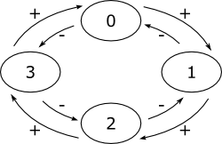
At a given time, the automaton is in one of the four states defined by the A and B signals. When one of the signals changes, the automaton switches to the new state, incrementing or decrementing the position counter:

Decoding, less resolution without losing steps
In the D flip-flop solution, the problem is that the increment is done on a different edge from the decrement. This solution address this problem.
When A is low, count up if B goes from 1 to 0, and count down if B goes from 0 to 1. Do nothing if A is high.
This solution give more accuracy than the single D flip-flop (i.e. does not lose steps) without the extra needed bits of the full automaton solution.